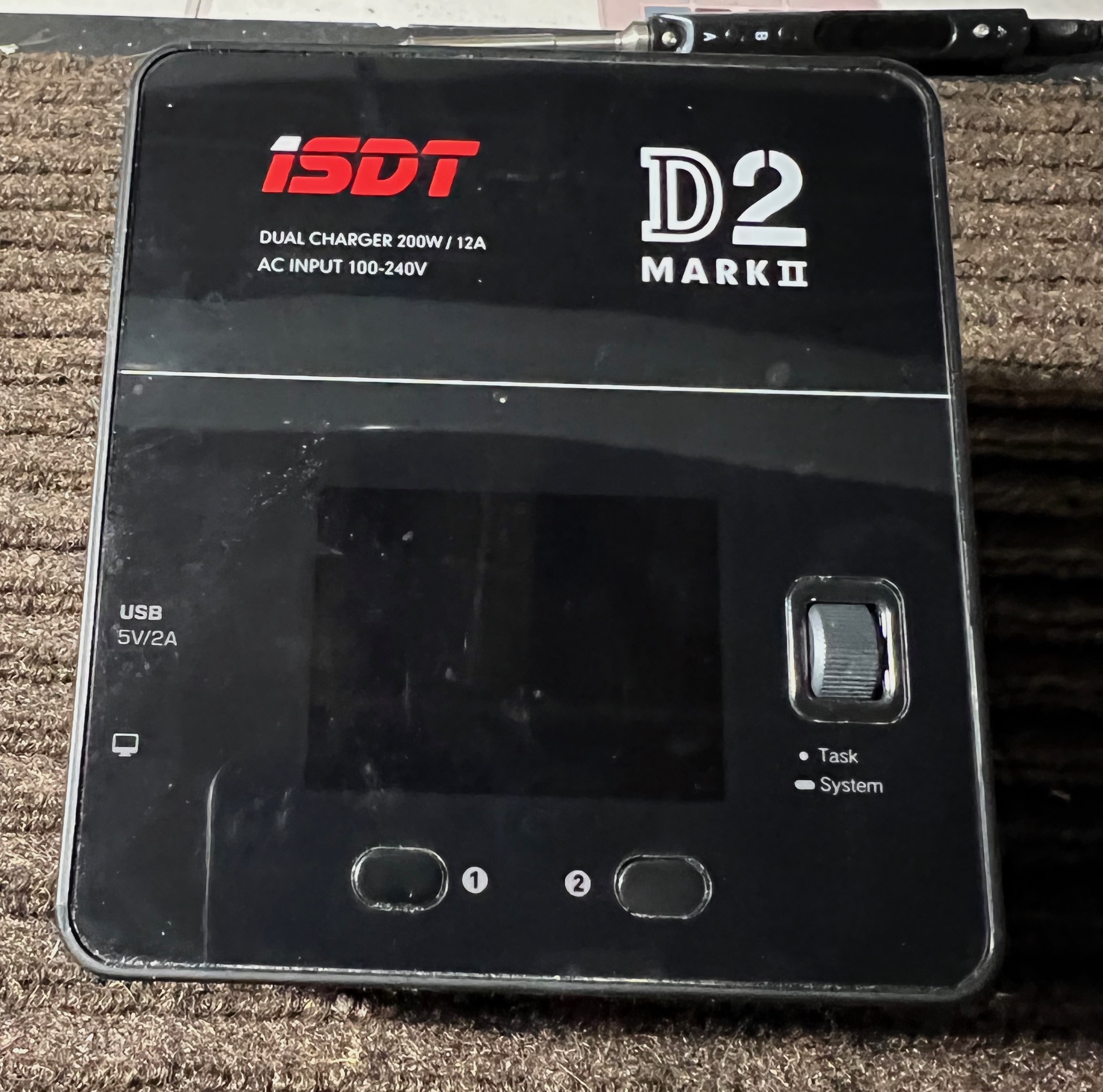
Adding DC Input to the ISDT D2 Mark II Charger
The ISDT D2 Mark II has been a great charger for me, with only one problem - it's AC powered only. This means it can't be used for field charging unless you have a generator or inverter nearby. I also can't power it via my existing DC power supply setup which powers all my other chargers. Let's fix that.
Looking over the charger you won't find any screws, ISDT usually hides them behind the faceplate. In order to access them we will have to first remove it. It is glued into place, but after warming with a heatgun it should peel right off.
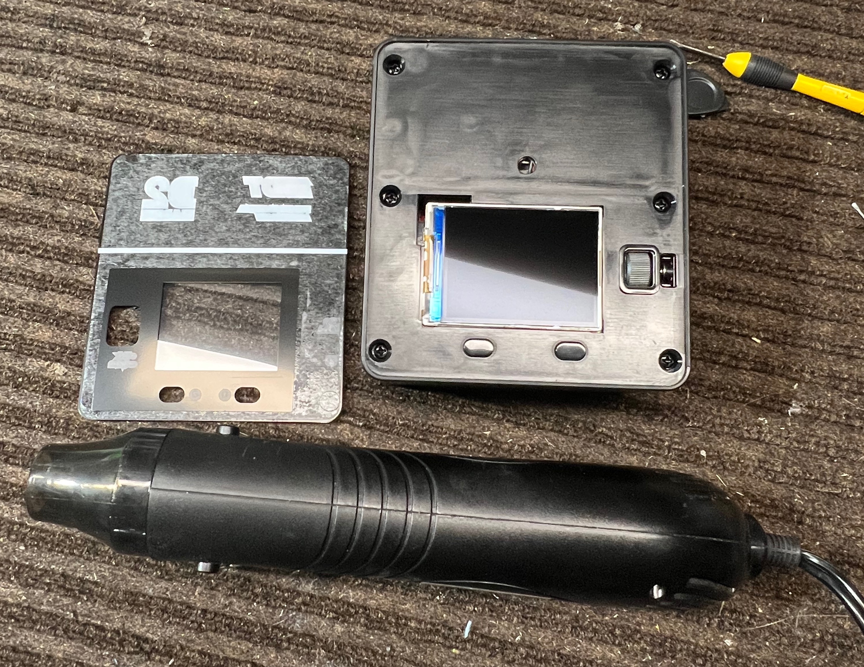
Once removed we can access the 6 philips screws. Remove them and carefully remove the top of the charger.
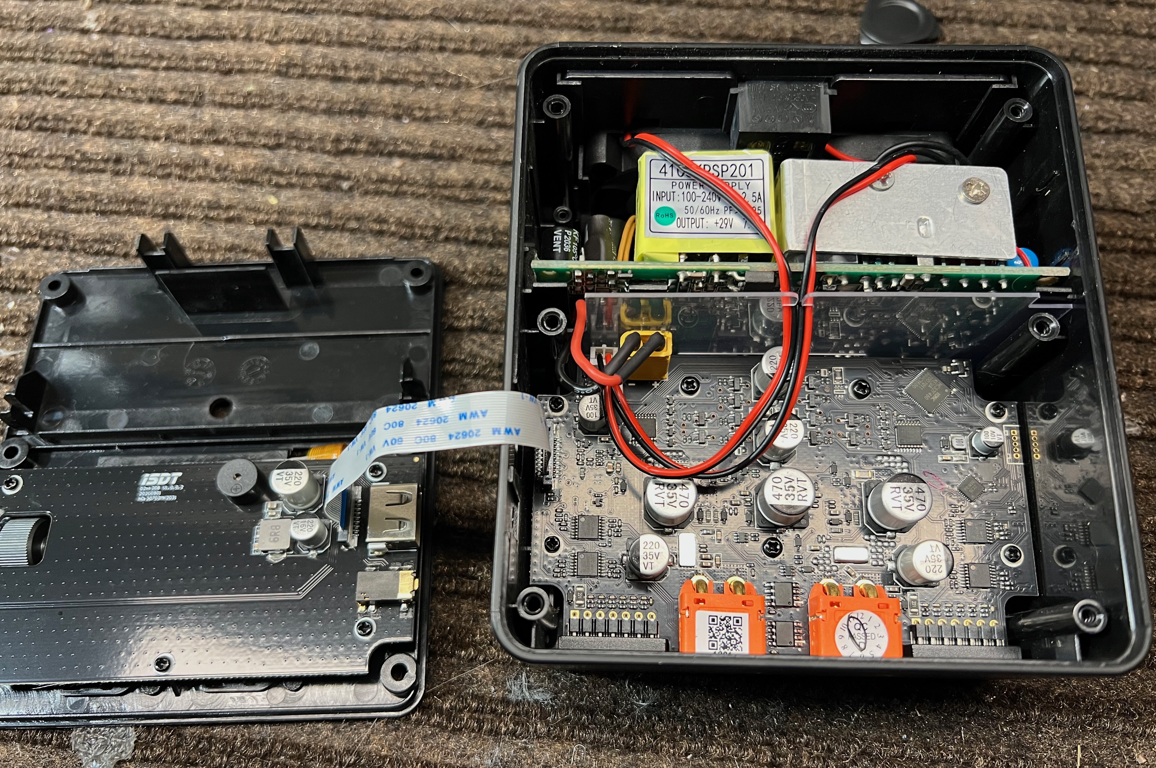
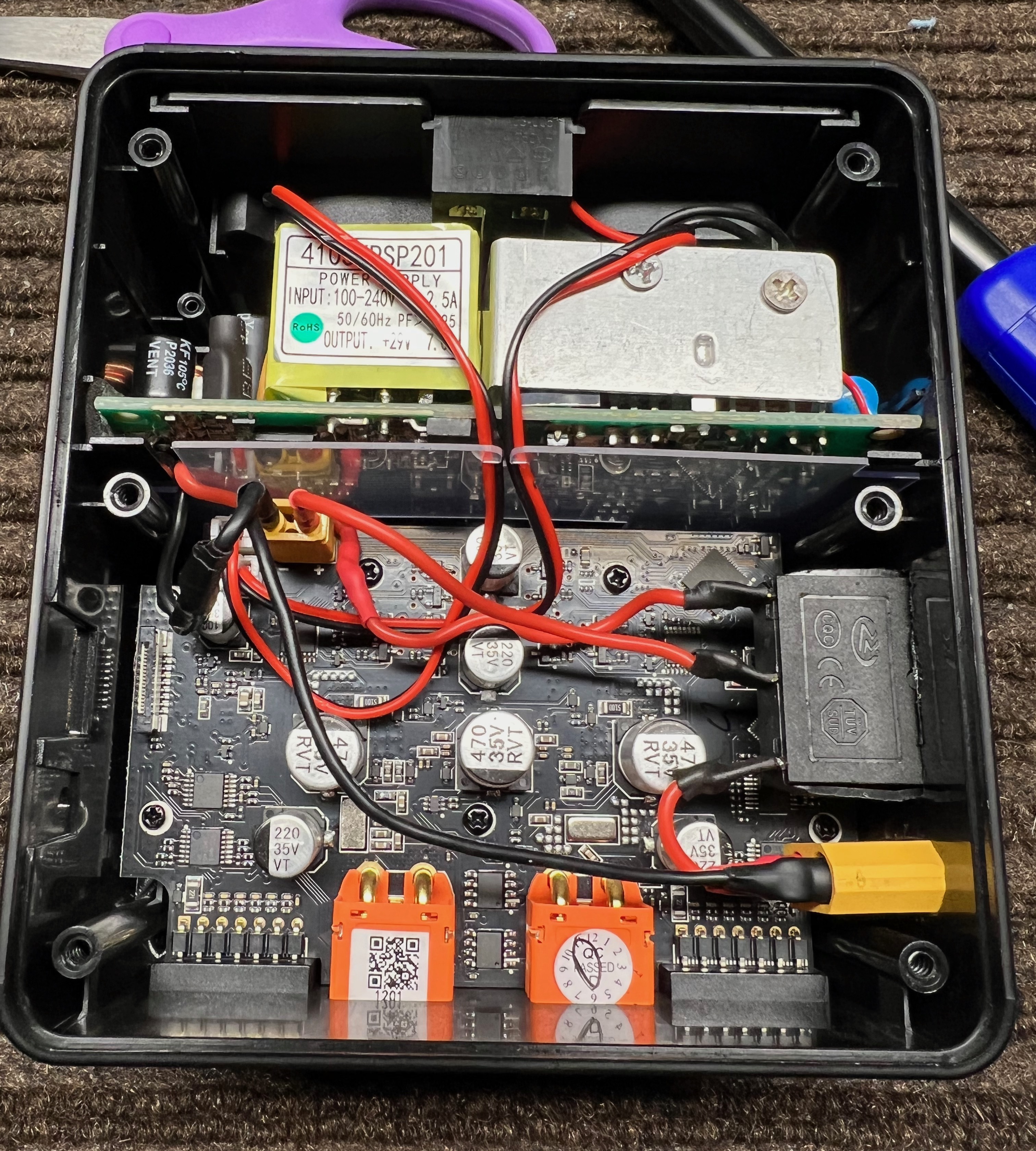
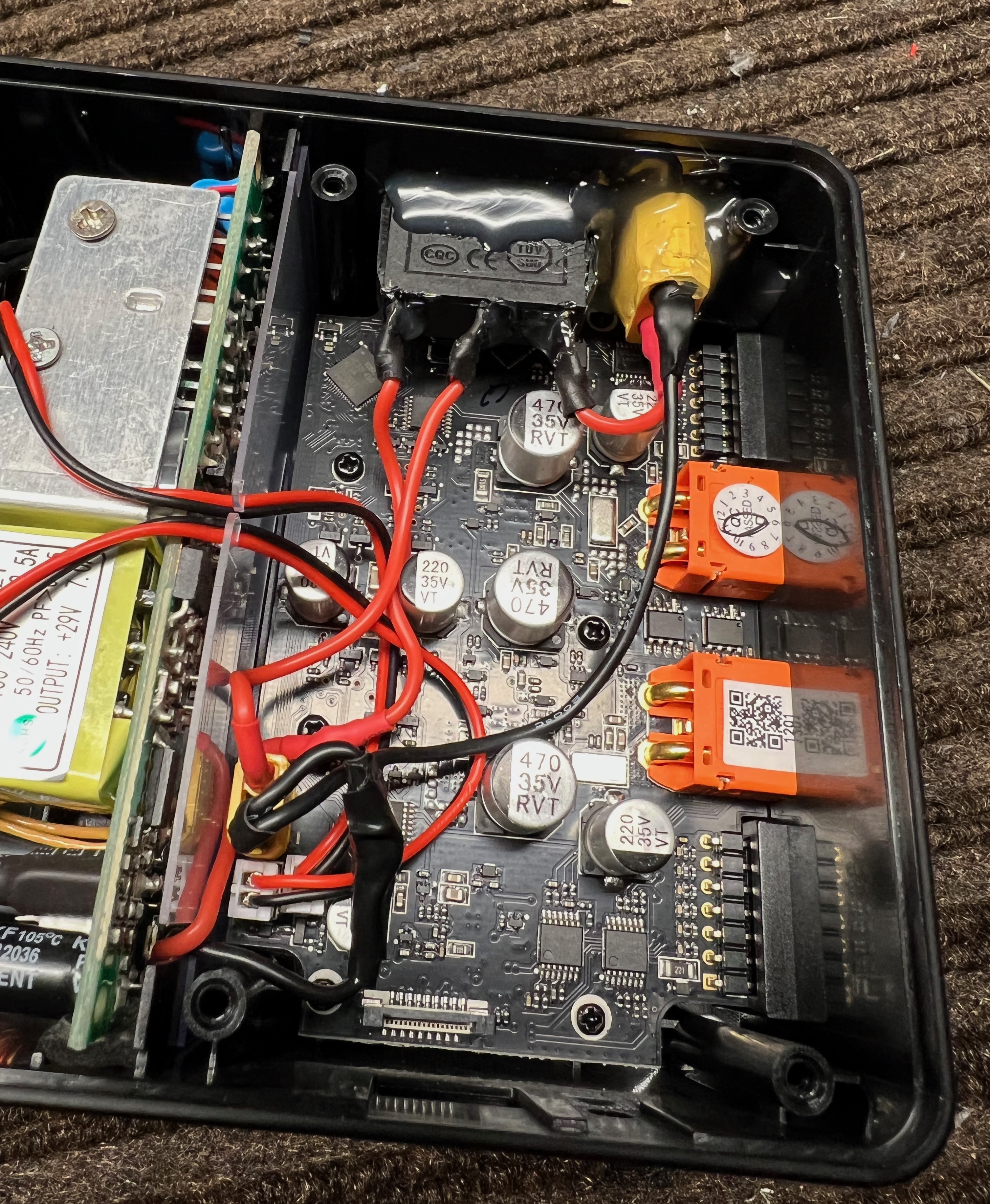
Once inside we can see that the charger is split up into 2 sections, the power supply side and the DC charging side. Conveniently it looks like ISDT uses an XT30 to link the power supply to the main board. After testing with a multimeter it is confirmed that the XT30 is supplying 29V DC.
Because 6S batteries are only 25.2V fully charged it means we should be able to power the charger with 6S batteries without any additional modification. So far it looks like this modification should be pretty simple.
My first thought was to just make a simple XT30 Y connector, but that would result in backfeeding the power supply when using battery input as well as supplying the input with 29V when using AC. This didn't seem like a safe idea, so I decided to wire in a switch to select DC or AC.
I found a 3 position toggle switch on Amazon that would fit in the available space & handle enough power: 5Pcs SPDT 3 Pins 3 Position ON/Off/ON Toggle Rocker Switch AC 15A/125V 20A/250V for Car Boat KCD3
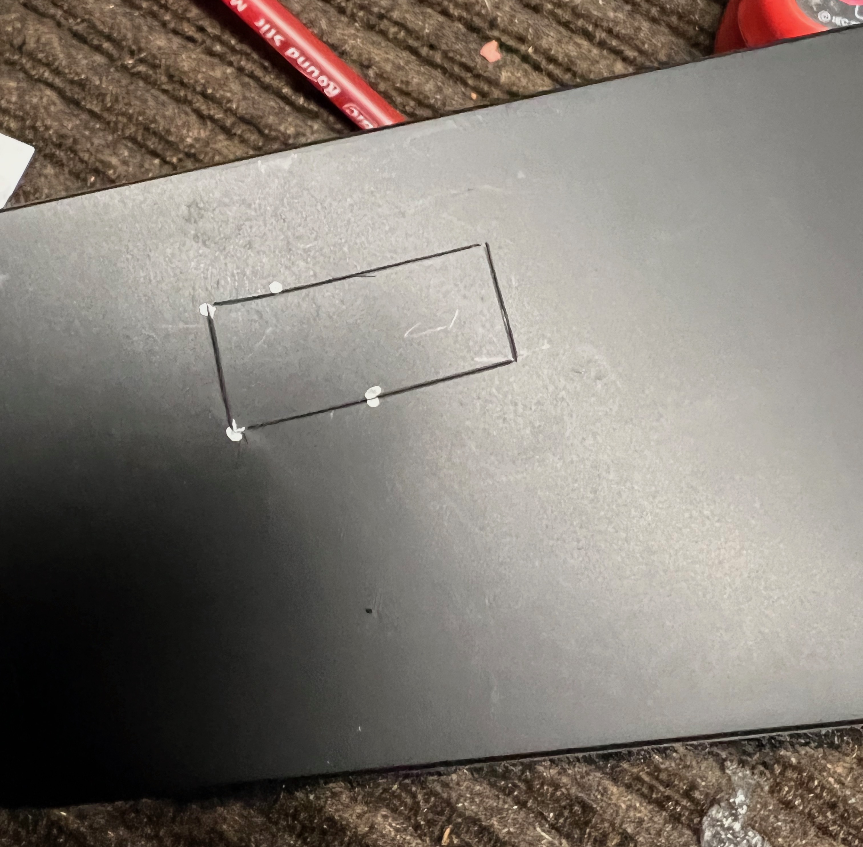
The right side of the charger had the most space available, so that is where the switch & DC input connector will be mounted. Using an X-acto knife I traced out the hole where the switch would go. Not pictured, but an XT60 was going to be used for the DC input so that got traced out too.
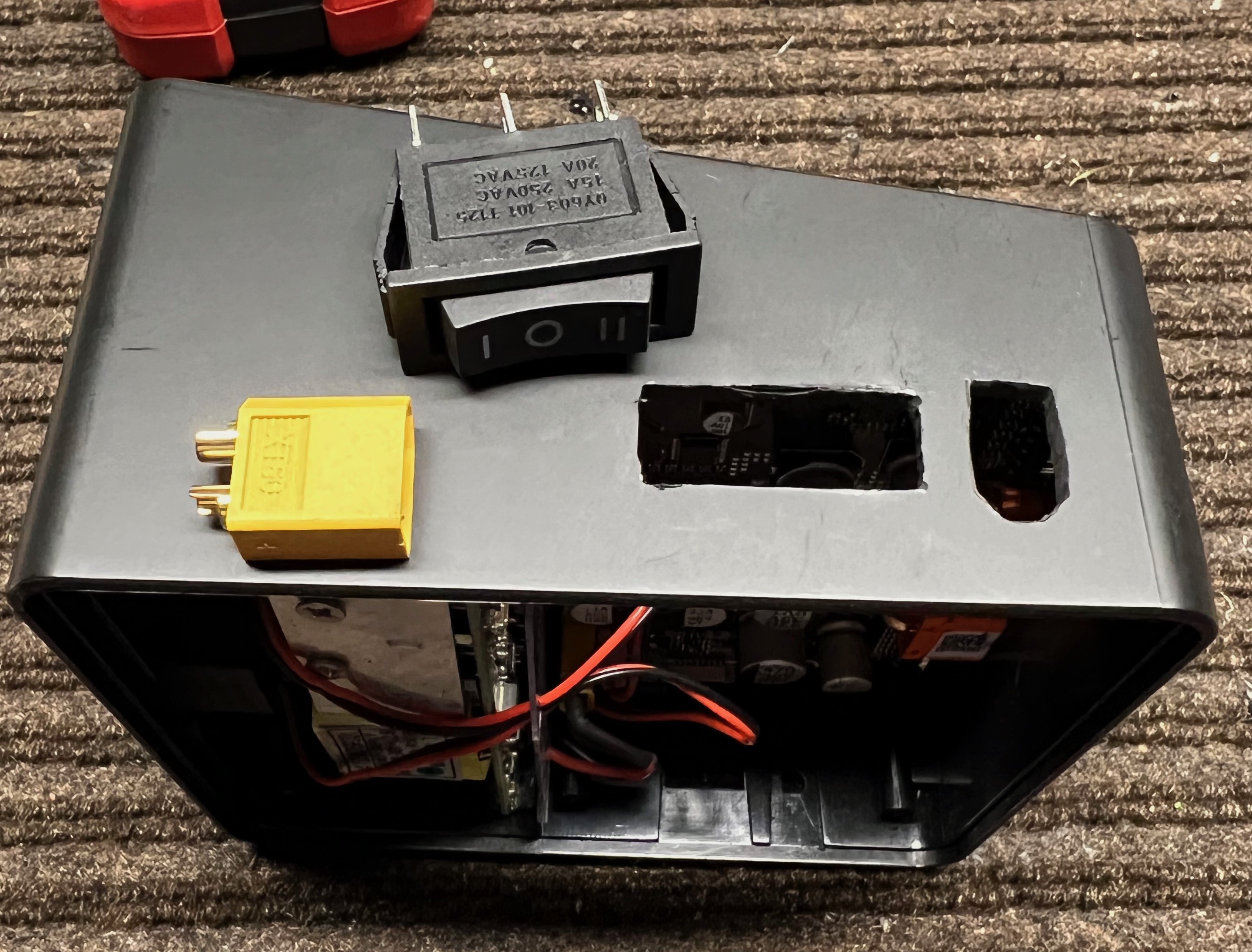
Using a dremel with a round bit it was easy to cut through the plastic & shape the holes.
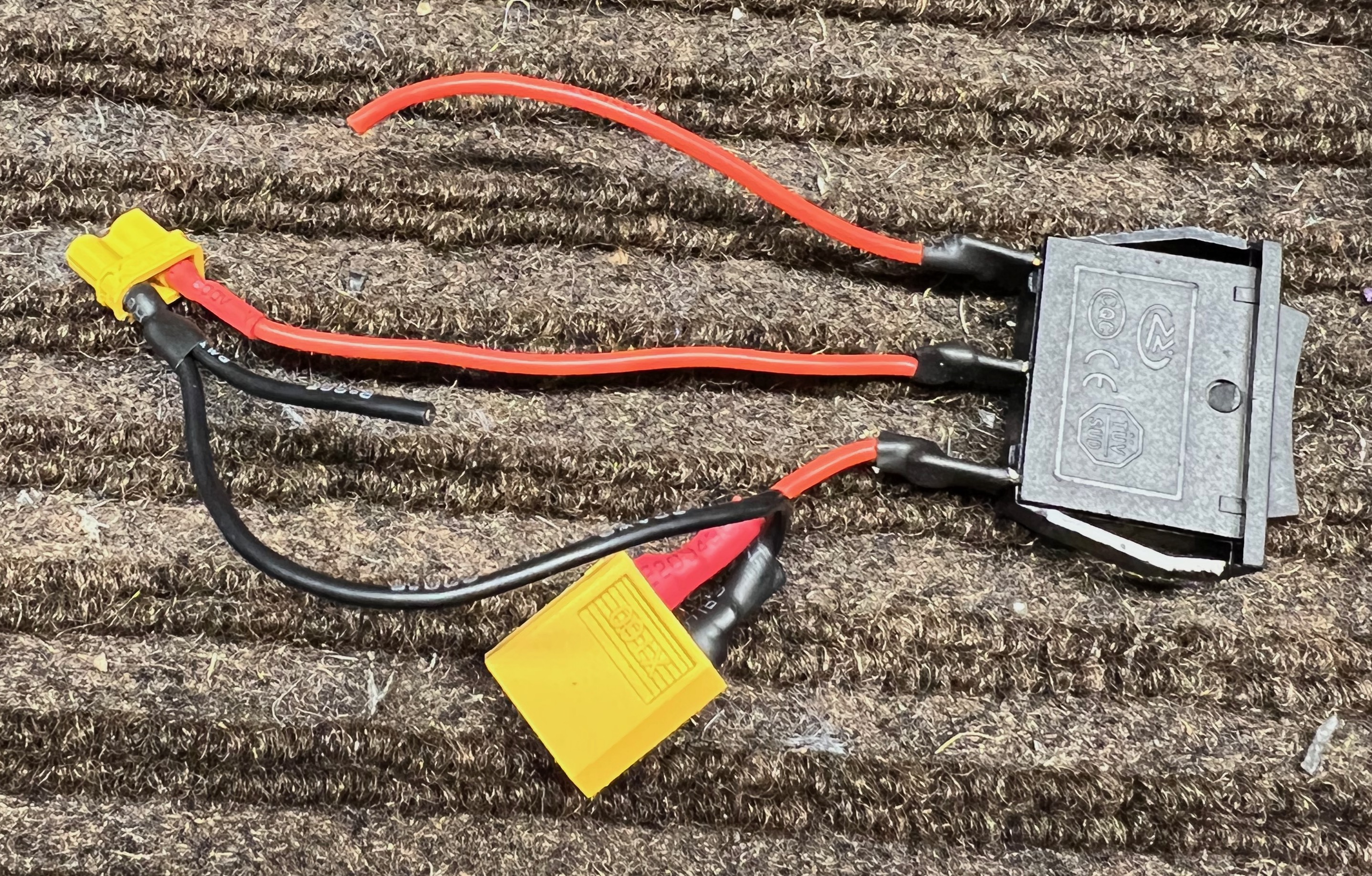
Most of the switch was wired before installing into the case because it's easier. The idea here is that the switch switches between the + (positive) output from either the internal power supplies output or the external input. The - (negative) from both sources is always connected to the negative leg of the XT30.
Slide the switch + XT60 into place. The last 2 connections, from the power supply to the XT30 negative & switch are made.
To keep the XT60 and switch in place, I used hot glue. A different type of glue would likely be better, but I think this will hold up fine as the fans provide good airflow to keep the glue from softening up. We'll see this summer.
Replace the cover + screws, then set the faceplate back into place.
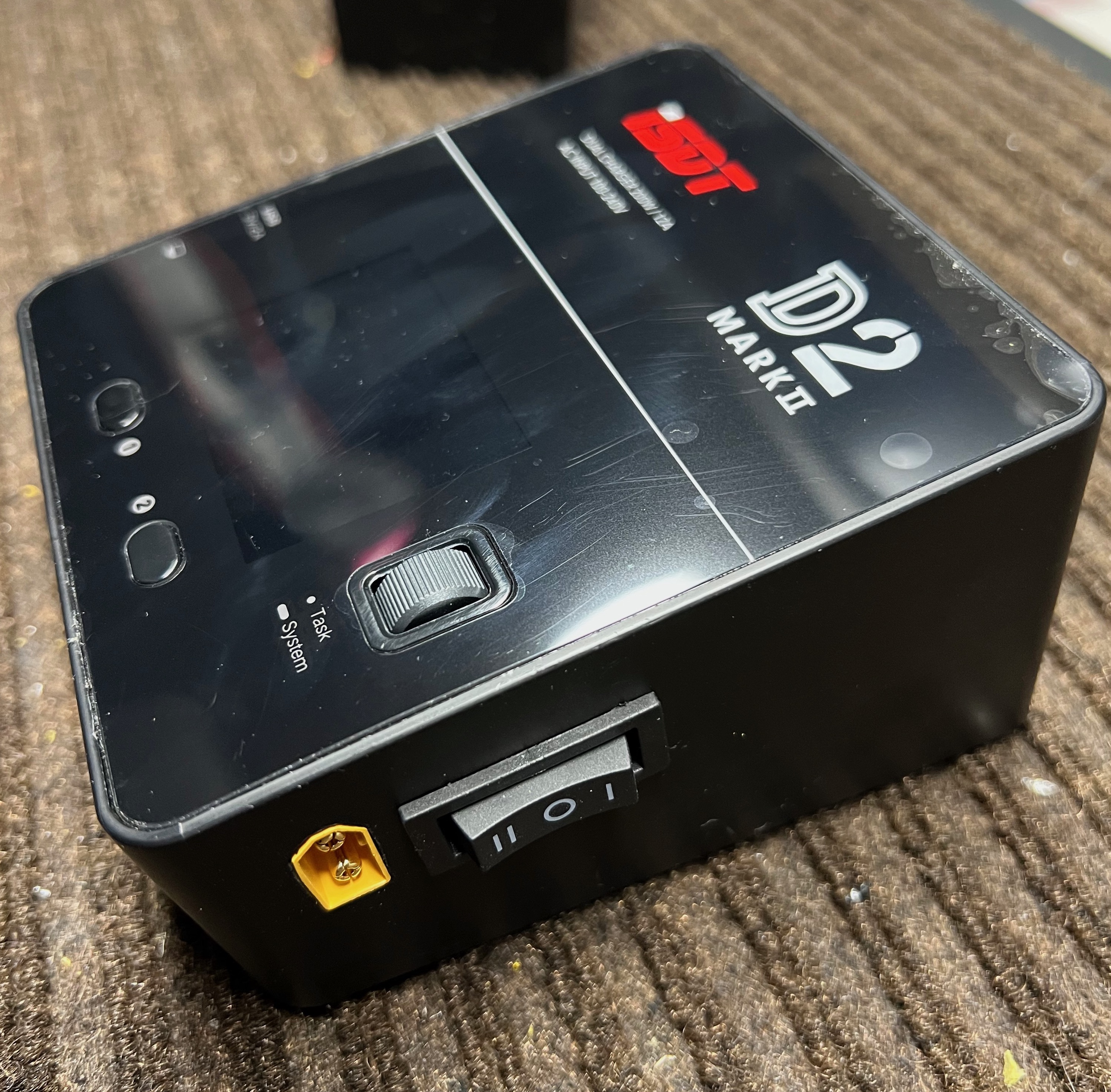
All closed up. The bubbling on the screen is just the screen protector.
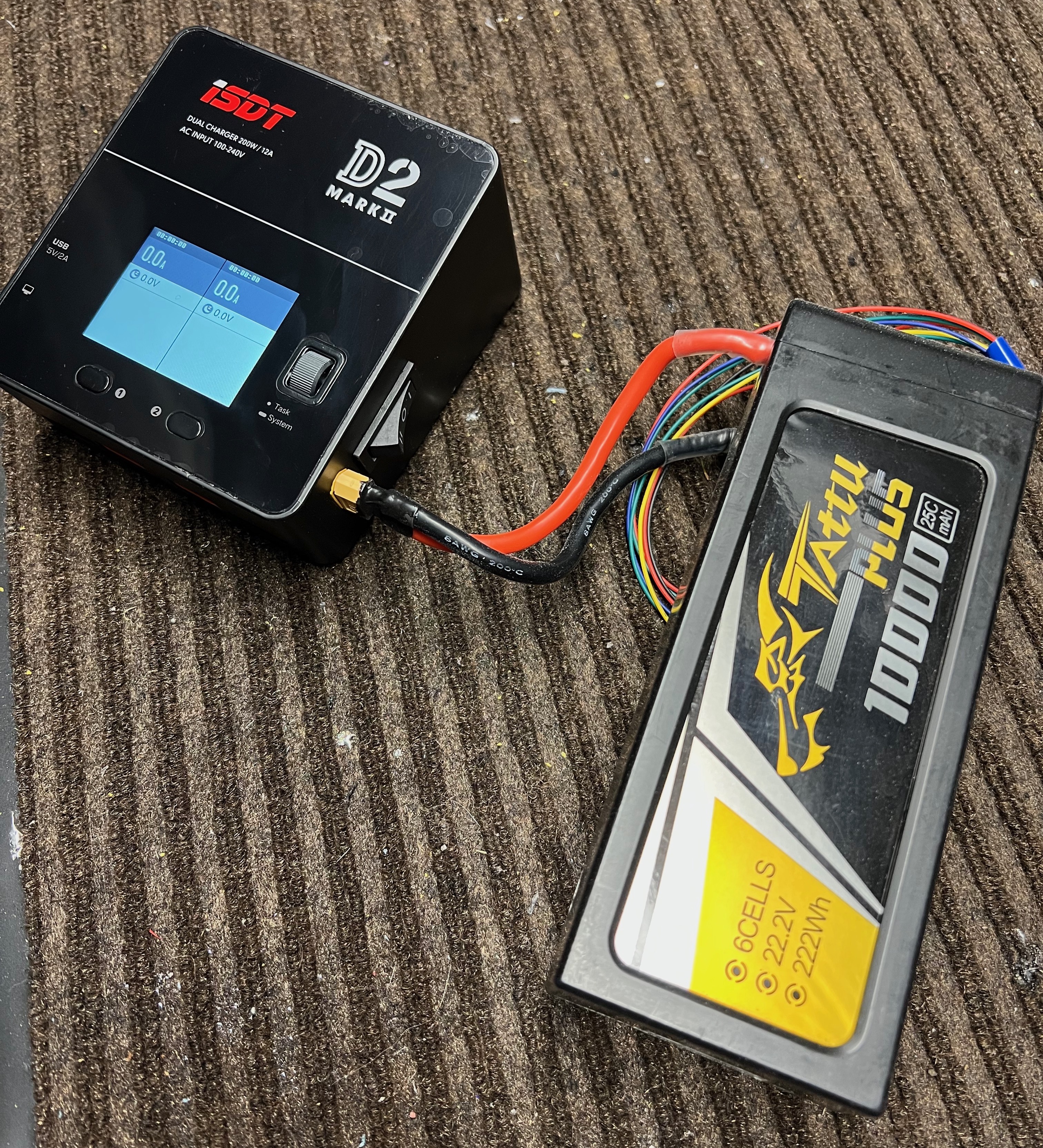
To test, I used my field charging pack. It was at this point I realized that the switch is sitting backwards, so back selects DC and forward selects AC - oh well. It's completely functional though, now the charger can be powered with its internal power supply via AC, or DC via an external supply.